

Urine Bottle & Sensor
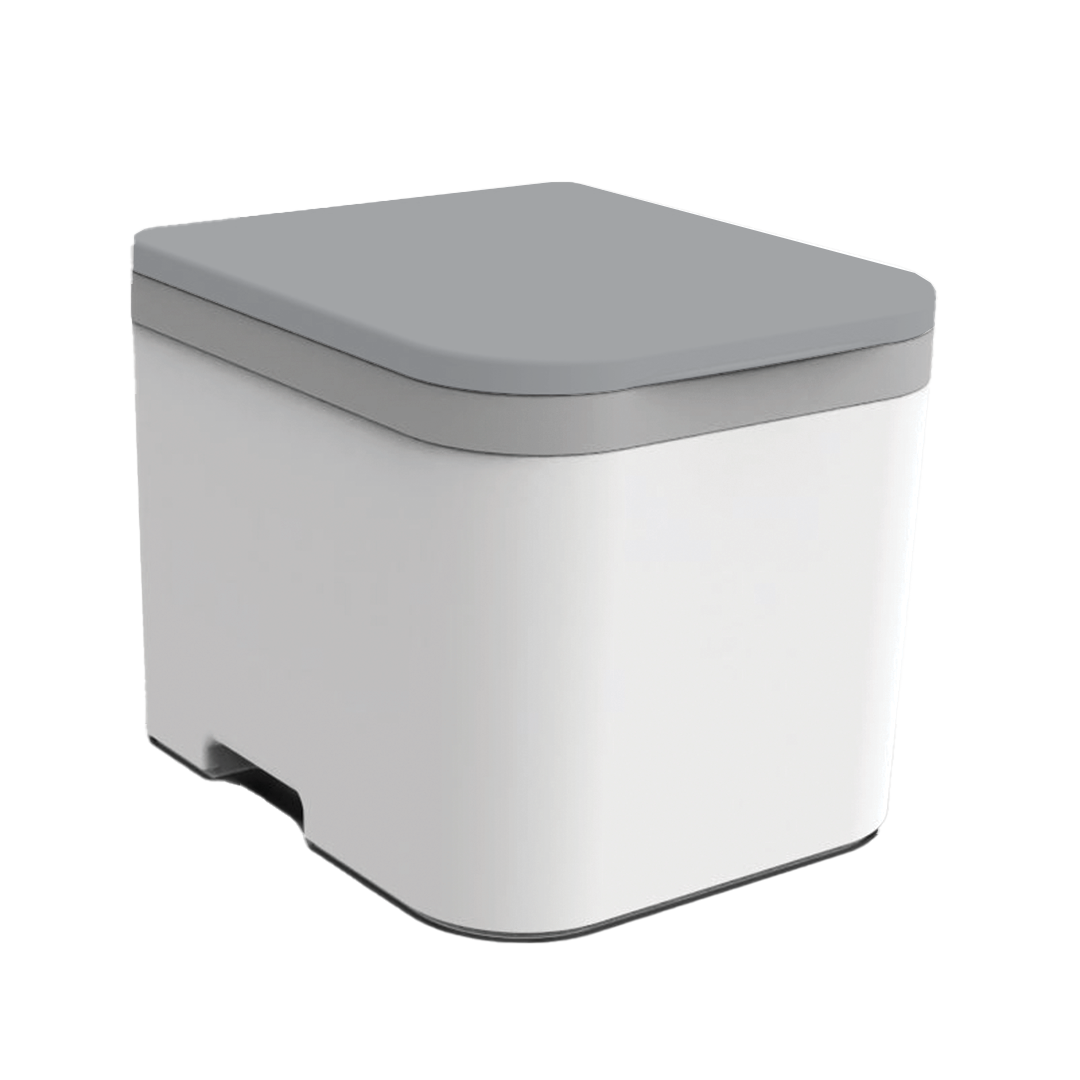
The urine bottle holds more than most compost toilets out there—2.4 gallons, to be exact. But what sets it apart is the built-in sensor and indicator light that tells you when it’s time to empty. No guessing, no overflow, no mess.
The OGO™ urine bottle holds 2.4 gallons and is made from durable HDPE plastic built to last. Each unit includes a bottle cap and a molded carry handle for easy transport.
To remove it:
- Unlock the drawer hooks on both sides. Or, you can remove the top with the drawer in place, too.
- Pull the drawer forward and remove the bottle.
- Cap it to prevent spills.
- Carry it out and dump it.
- Rinse with hot, soapy water after dumping. Optional: Add a splash of LemiShine once a week.
This one depends on where you are. Dumping laws and practices vary across cities, states, and countries. OGO™ users span over 40 countries, and every region is different.
That said, here are some common, safe, and eco-friendly options:
- Dilute it: Mix 1 part urine with 8 parts water and pour it on non-edible landscaping or mature trees.
- Use it as fertilizer: Urine contains nitrogen, potassium, and phosphorus—great for plants when diluted properly.
- Check local regulations: In some areas, it's legal to dump in nature; in others, it’s not. When in doubt, contact your local health or environmental department.
Recalibration is likely needed.
- Adjust the sensitivity dial as needed
- Use water for testing and make sure the light activates at the right time
Cleaning tip:
Use a damp cloth or swab. Don’t spray the sensor directly—wipe away any buildup gently.
1. Locate and Remove the Sensor
- Find the sensor behind the urine bottle on the left side. Gently push it forward out of its bracket.
2. Open the Sensor
- Use a small flathead screwdriver to remove the back cover. Inside, you’ll see a small silver adjustment dial(potentiometer).
3. Adjust the Dial
- If the LED is always on: Turn the dial clockwise to reduce sensitivity.
- If the LED never comes on: Turn the dial counter-clockwise to increase sensitivity.
- Make small turns and test after each adjustment. It may take multiple full rotations.
4. Test for Accuracy
- Remove the bottle and drawer. The LED (and the red sensor light) should turn off.
- Then place your finger or a full bottle in front of the sensor. The LED should turn on.
- Repeat several times to ensure consistent results. For best accuracy, test with water in the bottle—not just your hand.
5. Reassemble
- Snap the back cover on the sensor
- Reinsert it into the bracket
- Return the bottle and drawer to the unit
Still Need Help? Call us at 567-271-2020 or email support@ogotoilet.com. If we miss your call, leave a message—we’ll call back.
Yes. If you’d like to reduce the need for manual emptying, the OGO™ Drain Kit replaces the bottle with a hose that routes urine to:
- A sealed external container
- A greywater tank
- A drain field (where permitted)
This option is highly recommended for:
- Airbnb or guest installations
- Full-time use
- Remote setups where capacity matters
If you’re seeing urine where it shouldn’t be—outside the bottle, in the base, or seeping toward the solids bin—a water test can help diagnose what’s going on.
Directions:
1. Prepare the setup to make the drainage system visible.
- Remove the drawer, but leave the urine bottle installed.
- The bottle will sit slightly lower without the drawer, but it will still engage with the drain spout on the bottom of the toilet.
- This lets you clearly observe where the water goes as it enters the toilet.
2. Simulate Liquid Flow
- Slowly pour water into the front of the bowl, where urine would typically flow.
- Then, pour water near the back of the bowl with the trap door closed, to test less ideal but possible splash scenarios.
- Tip: This is much easier with two people! One person can pour water while the other uses a flashlight to watch the internal flow closely.
- If everything is working correctly:
- All liquid should flow into the urine bottle.
- No drips, puddles, or trickles should appear outside the bottle or base.
3. Test with the Trap Door Open
- Pour water into the rear of the bowl again.
- Observe where the liquid goes.
Expected behavior:
- Most urine hitting the rear separator will either trickle safely into the solids bin,
- Or, in rare cases, small amounts may flow to the front lip of the bin.
- This is intentional—OGO™ toilets are designed to minimize leakage even under less-than-ideal usage conditions.
Solids Bin
You can remove the bin in one of two ways (use whichever works best for your space):
- Top access: Lift the lid and housing, then lift the bin straight out.
- Front access: Unhook the drawer locks, remove the urine bottle, and pull the bin out from the front.
Once it’s out, you have options:
- Compostable bag method: Use a 4-6 gallon compostable bag or plastic bag. Place it over the bin and turn the bin upside down. Tap the solids bin on the bottom and sides to break up the mixture for easy dumping. Toss it in the trash (if allowed), or empty it into a long-term compost pile.
- Direct dump method: Skip the bag and empty the contents directly into your compost site.
Compost reminder: Waste continues to break down after it leaves the bin. Full composting takes 6–12 months. Rotate piles and balance your compost with dry materials like leaves, food scraps, or wood chips for best results.
- To refill: Add 24 oz. of compost medium. If water is needed, slowly add a small amount. Mix lightly, aiming for a damp, airy texture.
- Tip: The bin isn’t watertight. Add water slowly to avoid leaks. If the mix dries out or gets dense over time, add a splash of water to fluff it back up.
Keep the lid closed when not in use, and always make sure the airflow is running.
The compost medium mixes with waste to reduce odor and start the breakdown process. For the OGO™ ORIGIN, the right medium is key.
Use:
- Coco coir (recommended)
- Sphagnum peat moss (a good alternative)
Peat Moss is easy to find, light, and absorbent. Use it damp, not wet.
Coco Coir handles moisture better, lasts longer, and is more consistent. It’s the best choice if you're using your toilet frequently or full-time. We sell 24 oz. pre-moistened coco coir bags for convenience. Or, grab a dehydrated brick at any garden center—just rehydrate and portion it out.
Avoid:
- Wood chips or shavings
- Straw or hay
- Cat litter
- Sawdust
- Grass, leaves, soil, ash, pine needles
These materials can clog the agitator or reduce airflow, leading to odor or damage.
Use about 24 oz. of medium per fill. It should be light, fluffy, and just slightly damp—never soupy or powder-dry. A little moisture helps mix everything smoothly and breaks down toilet paper better.
For the ORIGIN, the sweet spot is 24 oz. of dry coco coir or sphagnum peat moss. This amount provides the right depth and density for solids to be effectively mixed by the internal electric agitator.
Our recommendation: Slightly moisten the coir. Not wet—just enough to reduce dust and help paper break down more evenly. Think damp sponge, not soggy soil.
Note: When using the OGO™ ORIGIN Compost Toilet System, use only coco coir or sphagnum peat moss. Other materials may clog or damage the agitator due to improper consistency.
Note: Too much compost medium can clog the agitator in electric models or reduce capacity in bag-based systems. It’s tempting to overfill "just in case," but trust the process—less is more when the medium is right.
Add your medium after each full emptying of the solids bin. 24 oz. of coco coir will typically get you 25–30 uses per cycle.
The NOMAD system is manually layered—no electric mixing, just a smart sequence of compost medium and waste. One 24 oz. bag of compost medium gets you about 8–10 uses, depending on how consistently you layer.
Layering instructions:
- Start with a fresh compostable bag and a base layer of compost medium.
- After each use, add a small scoop of medium to cover waste.
- Repeat until the bag is about ⅔ full.
- Tie off the bag and discard responsibly.
This method is low-tech, low-maintenance, and ideal for weekenders, emergency kits, and compact mobile setups. The key to success? Consistency. If you skip layering or overload the bag, you’ll cut capacity and invite odor.
Yes, you can — but there are a few important details you need to know first. The Nomad wasn't originally designed around a dedicated solids bin, but there’s enough room to make it work if you size it right.
Ideal Solids Bin Size:
- 9" x 9" footprint
- 7.5" max height
- Any bigger, and it won’t fit cleanly — it’ll hit the handles, the bottle, or the underside of the bowl.
Quick DIY Fit Test
- Cut a 9" x 9" cardboard square.
- Test fit it at the bottom of your Nomad.
- Stack it 7.5" tall to check clearance under the bowl.
- If it fits, your bin will too.
Likely, the bin isn’t properly seated into the motor cog, and the agitator arm is not spinning. Check that the bin is inserted fully and aligned.
Under normal use, your composting medium (like coco coir or peat moss) should absorb any residual moisture, especially small amounts of urine that might bypass the separator. The system is designed so that liquid should never rise to the agitator. If it does, something’s wrong—and we want to help.
Contact us if you notice:
- Liquid is collecting in the bin
- Saturated or pooling compost
- Moisture high enough to reach the agitator
Include your purchase info so we can assist quickly and accurately. We stand behind every unit—and we’re here to keep yours performing as it should.
Power Issues
Check your wiring. Most problems come down to polarity—just like putting batteries in backwards. In older units, incorrect wiring can trip the PTC fuse, damaging the timer.
Tip: If your motor isn't spinning, not running the full cycle, or sounds off, contact us. We’ll help troubleshoot and get you replacement parts fast if needed.
1. Double-check your polarity:
- Red = Positive (+)
- Black = Negative (−)
2. Make sure your fuse or breaker is not tripped
3. Verify the barrel plug is fully inserted into the unit
4. Test the line with a multimeter for voltage (should read 12V-14V DC)
Directions:
- Unplug the Unit: Always disconnect the 12V DC input before working inside the unit.
- Locate the Power Jack: Reach behind the front panel where the jack enters the housing.
- Inspect the Wires: Check that the red (positive) and black (ground) wires are fully seated in the connector. If the unit uses a WAGO® clip, press the orange tabs and confirm clean contact.
- Check the Jack Fit: Make sure the jack isn’t loose inside the panel. A poorly seated jack can cause intermittent loss of power.
- Plug Back In and Test: Reconnect the 12V supply and test the unit. If the fan, LED, or button still doesn’t respond, the issue may be upstream — power adapter, fuse, or the jack itself.
Next steps if power still fails:
- Check your power adapter (output should be 12V DC)
- Inspect fuse (if your install uses one)
- Email support if the jack or wiring looks damaged or if there are ongoing issues.
If the motor is running but the agitator in the solids bin isn’t moving, the black cog is likely stripped.
- Remove the solids bin.
- Unscrew the bolt holding the black plastic cog.
- Check the hex-shaped socket. If it’s rounded out, cracked, or slipping, the cog is done. And needs to be replaced. Contact us, and we’ll ship you a replacement.
If the motor isn’t making any sound, you’re dealing with a power issue.
1. Start with the power source:
- Battery users: Confirm the battery is charged.
- Wall power: Ensure it’s 12V DC and can handle up to 10 Amps. Many power supplies only deliver 1–3A, which isn’t enough to run the motor.
- Buy Power Adapter from OGO
2.Check the power jack:
- Look inside the jack for corrosion, a loose fit, or burnt contacts.
- Inspect the power jack
- Replace the power jack
3. Open up the base:
- Remove the cone insert to access the motor and timer wiring.
- Access the wiring
- Inspect all WAGO® connections and look for corrosion, dislodged wires, or signs of moisture damage.
4. If everything looks clean but the motor still doesn’t run, bypass the timer temporarily to test the circuit.
- If the motor runs with the bypass, you need a new timer.
- If it still doesn’t spin, test the motor directly: Connect the motor directly to a 12V DC power source (rated for 10 Amps). If it doesn’t respond, the motor itself needs to be replaced. Let us know—we’ll get one out to you.
If your agitator isn’t spinning, don’t stress—it’s easy to pinpoint the cause.
- Bypass the timer and send power straight to the motor.
- Connect the motor wires directly to your 12V power supply. We show you how in the video.
- If the motor spins counterclockwise right away—it’s good, and the issue is elsewhere. Next possible causes: loose wiring, stripped cog, faulty timer
- If the motor doesn’t spin—it’s the motor. We’ll help you get a replacement.
- If you purchased from us directly, you’ve got a 3-year warranty. Email sales@ogotoilet.com and we’ll make it right.
- Is your adapter truly 10 Amps? Low-amp adapters (1A, 2A) won’t run the motor.
- Are your wiring connections secure? Re-check every snap connector with a light tug.
- Still not spinning? Test the motor directly with a bypass.
- If the motor doesn’t spin when powered directly, it’s the motor. We’ll get a replacement sent out.
- Still Need Help? Call us at 567-271-2020 or email support@ogotoilet.com. If we miss your call, leave a message—we’ll call back. You’ve got a 3-year warranty if you bought from us directly.
Bypassing the timer is useful when:
- Your unit isn’t starting or cycling as expected
- You’re not sure if the timer or the motor is causing the issue
- You need a quick way to confirm motor function before replacing parts
- This is a diagnostic step, not a permanent setup.
Bypass Method for Units with the Original Timer (Pre-August 2022)
- Disconnect the green wire from the timer. This removes the start trigger and allows the motor to activate in semi-automatic mode.
- Apply 12V power directly to the motor if further testing is needed.
- Check for movement or motor response. If the motor runs, the issue is likely with the timer.
Bypass Method for Units with the New Timer (Post-August 2022)
- Disconnect the green wire from the new timer (same as the older version).
- You can also apply 12V directly across the white (motor output) and black (ground) wires to test the motor independently.
- Make sure you reconnect everything properly after testing.
Safety Note
Always ensure the power is off before adjusting wires. Use caution when testing with live 12V power, and double-check your connections before reapplying power to avoid shorting components.
Still Not Sure? If bypassing the timer confirms your motor is working but the unit still won’t cycle normally, your timer may need to be replaced. Email us at sales@ogotoilet.com
You might have this issue if:
- The motor or fan doesn’t activate
- The timer appears dead despite a good power source
- The toilet only works in semi-automatic mode
- All wiring appears correct, but the unit won’t run
- If these signs sound familiar—and your unit is from before August 2022—you’re likely dealing with a damaged original timer.
Temporary Fix: Semi-Auto Mode
If you need a short-term workaround while waiting for a replacement timer, unplug the green wire from the timer. This bypasses the start-trigger signal and allows your OGO™ to operate in semi-automatic mode.
If your timer failed due to reverse polarity and your unit is still under warranty, contact our support team. We’ll help verify the issue and send a replacement timer if eligible. Be ready to provide:
- Your unit’s serial number
- Description of the issue
- When the problem started
- Unplug the toilet.
- Always disconnect the power before opening anything inside.
- Remove the solids bin and agitator cone.
- Just lift both out as you would for cleaning.
- Remove the base cone insert plate.
- Find the angled plastic panel at the bottom.
- Unscrew the 2–4 Phillips screws holding it in.
- Gently lift the plate out.
You’re in.
The motor and timer wiring are now fully visible and accessible.
Take a photo before unplugging anything—it’ll make putting it back together way easier.
Parts Replacement
What You Need:
- Replacement fan housing (fan + filter)
- Optional: flathead screwdriver (for WAGO® clip)
Directions:
- Unplug Power: Disconnect the toilet from its 12V DC source. Always.
- Open the Lid: Lift the bowl lid. No hinges or tools needed.
- Remove the Fan Housing: The fan is in the rear-right vent channel. Lift it straight up — no screws. Slide the fan out of the housing if needed.
- Disconnect Wiring: Fan wires connect with a WAGO® clip. Press the orange lever and pull the wires free.
- Install New Fan: Slide the new fan into the housing. Make sure it blows air out of the vent. Press wires back into the same WAGO® slots.
- Drop It Back In & Test: Push the housing back into the vent.
- Plug in power: Fan should run immediately — feel for airflow.
Note:
- Every housing includes a molded debris filter with metal mesh that is built-in, sturdy, and replaceable. It helps protect the fan and keep air clean.
- Our wiring has changed over the years as we continue to optimize our products. If you need a previous version of a wiring diagram, you can find it here or reach out and customer care can help get you the correct one for your unit.
What You Need
- OGO Origin Replacement Power Button
- ¾ inch wrench (to remove the mounting nut)
- Flathead screwdriver (optional for connector release)
Directions:
- Disconnect Power: Unplug the toilet from the 12V DC source.
- Access the Button: Reach behind the front panel from inside the unit. Locate the mounting nut and wire connector.
- Disconnect Wires: Press the orange tab on the connector and pull the wires out. Use a flathead screwdriver if needed.
- Remove the Button: Use a ¾ inch wrench to loosen and remove the nut. Push the button out from the front.
- Install the New Button: Insert the new button into the panel. Tighten the nut by hand, then snug it with the wrench. Reconnect the wires in the same positions.
- Reconnect Power and Test: Plug the unit back in. Press the button to confirm the cycle starts. Fill the bottle to verify the LED indicator turns on when full.
Note:
- Our wiring has changed over the years as we continue to optimize our products. If you need a previous version of a wiring diagram, you can find it here, or reach out, and customer care can help get you the correct one for your unit.
What You’ll Need
- Replacement 12V DC barrel jack
- Wire strippers or a utility blade
- Flathead (optional) for WAGO® clip release
Directions:
- Disconnect Power: Unplug the unit from its 12V DC power source.
- Access the Power Jack: Reach inside the housing and push the jack out from the panel. Most versions are pressure-fit or secured with a nut you can turn by hand.
- Disconnect Wiring: If your jack is wired into a WAGO® connector, press the orange tab and pull the wires free. If wires are wrapped or shrink-wrapped, gently separate them and expose the individual red and black wires.
- Remove the Old Jack: Once wiring is disconnected and the jack is loose, pull it fully out through the front panel.
- Prep the Wires: If your replacement jack doesn’t come pre-wired, you’ll need to attach your own wires. Strip back the outer plastic coating if needed to expose the red and black wires inside. Then strip about ¼" off the ends to make clean connections.
- Connect to the New Jack: Match wire colors: Red to +12V, Black to Ground Insert wires into the WAGO® clip and secure by closing the orange clip.
- Install and Test: Seat the jack back into the panel opening. Tighten the bolt around the jack by hand then secure it with a wrench. Do not over torque.
- Plug the unit into power.
- Check for function: fan turns on, button triggers cycle, LED lights up.
Note:
- Our wiring has changed over the years as we continue to optimize our products. If you need a previous version of a wiring diagram, you can find it here or reach out and customer care can help get you the correct one for your unit.
What You Need:
- Replacement 12V DC motor (compatible with OGO Origin)
- Phillips screwdriver
- Flathead screwdriver or small pry tool
- Wire strippers
- WAGO® clip or crimp connectors
Directions:
- Disconnect power before doing anything.
- Open the lid and access the motor area inside the unit. Depending on your version, there may be a small cover or shell to remove.
- Once open, locate the motor—it's mounted under the solids bin and held in place with screws or a bracket.
- Unplug or release the wires from the WAGO® clip. If your motor is hardwired, cut the leads close to the body so you have working length for reconnection.
- Unscrew the motor and remove it from the housing.
- Slide in the new motor and resecure it using the original mounting points. Make sure the stir shaft aligns and rotates freely.
- Strip the wire ends if needed and reconnect red to red (+12V), black to black (ground).
- Reuse the WAGO® connector or crimp a secure join.
- Reconnect power and run a test. The button should trigger a full 45-second cycle. If the motor doesn't start or makes irregular sounds, recheck wire polarity and mounting alignment.
What You’ll Need:
- Phillips screwdriver
- Replacement cog (contact us if needed)
- Washer and bolt (reuse original unless damaged)
Directions:
1. Remove the old cog
- Flip the solids bin upside down. Unscrew the bolt from the bottom and remove the washer.
- Pull the agitator out. If the cog is loose, it may fall out. If tight, give a gentle pull to remove it from the hex coupling nut.
2. Reassemble in this order—top to bottom
- Bolt
- Washer
- Cog (recessed lip up, seated around the molded lip of the solids bin center, aligned with hex coupling nut)
- Blue bearing ring (if included)
- White bushing (flat side up)
- Agitator shaft
- Important: The cog should sit flush around the central lip inside the solids bin. This ensures smooth rotation and keeps the agitator properly centered. If the cog is not seated fully or is off-angle, it may cause friction or misalignment.
3. Secure and test
- Hand-tighten the bolt until snug. Do not overtighten.
- Manually rotate the agitator to check for free, unobstructed movement.
What You’ll Need:
- Replacement timer (should come pre-wired)
- Small flathead screwdriver (to help pry and release connections)
Directions:
1. Remove the Old Timer
- Start by identifying the existing timer. It’s usually held in place with adhesive or clips.
- Pry it loose: Gently lift the old timer using a flathead screwdriver if needed. Be careful with the wires.
- Disconnect the wiring: The timer should have lever-style connectors. Lift these to release the wires. You’ll typically see four color-coded wires (red, black, green, white).
2. Install the New Timer
- Before mounting the timer, connect the wires one at a time using the lever connectors on the new unit:
- Red to Red – This is your 12V hot line. After snapping the lever down, give a gentle tug to ensure it’s secure.
- Black to Black – This is your ground connection.
- Green to Green – This wire acts as the input trigger, allowing the timer to start.
- White to White – This is the output current that powers the motor.
- Once all wires are securely in place, remove the protective tape on the back of the new timer.
3. Mount the Timer
- Find a clean, flat surface in the original mounting area. Press the timer down firmly so the adhesive sticks well. Make sure no wires are being pinched or stressed.
4. Final Check
- Tug gently on each wire to confirm secure connections.
- Double-check that colors are matched correctly.
- Ensure the timer is seated firmly.
Tools You’ll Need:
- Wire cutters or scissors (for zip ties)
- Replacement sensor (Contact us if needed)
- Zip ties (optional, for securing wires after installation)
Directions:
1. Remove the Old Sensor
- Lift and expose the sensor area.
- The sensor has three wires attached to it. You may find it easier to unmount the sensor before unplugging the wires.
- Cut any zip ties holding the wires in place.
- Carefully snip the zip ties to free the wire bundle and give yourself some slack.
- Disconnect the sensor wires.
- The wires are connected using lever connectors. Lift the orange lever tabs to release the wires.
- Yellow → Yellow
- Brown (may appear reddish) → Red
- Blue → Ground (black or brown in some systems)
2. Install the New Sensor
- Prepare the new sensor and unwrap it.
- Confirm the wire colors match the original sensor: yellow, brown/red, and blue.
- Reconnect the wires using the same lever connectors:
- Push each wire fully into its slot and snap the lever tab down.
- Double-check that each connection is secure and snug.
3. Re-Route and Secure the Wires
- Route the sensor cable along the original path, tucking it neatly into the groove or channel.
- Loop the cable behind the triangular tab section where the cover has a built-in relief for it.
- Add fresh zip ties to secure the cable and prevent movement during use.
4. Final Check before replacing the cover
- Confirm all wires are connected correctly.
- Check that the sensor is seated and oriented properly.
- First-time sensor? Make sure it’s calibrated correctly.
What You’ll Need:
- A small flathead screwdriver or pin punch
- A replacement lid for the OGO Origin
- (Optional) A small hammer or mallet for light tapping
Directions:
1. Remove the Damaged Lid
- The OGO Origin lid is secured with a hinge pin. To remove it:
- Insert your screwdriver or punch into one end of the hinge pin.
- Push the pin until it begins to slide out the opposite side.
- Once exposed, pull the pin out completely.
- Lift the lid off the toilet base.
- If the pin feels stuck, gently wiggle your tool or apply light pressure until it moves.
2. Install the New Lid
- Align the new lid’s hinge holes with the openings on the toilet body.
- Slide the hinge pin back through the holes, keeping everything lined up.
- Push the pin in by hand or use a small mallet to tap it gently into place.
- Make sure the pin sits flush and even on both sides.
3. Test for Fit
- Open and close the lid a few times to ensure it moves smoothly and the hinge pin is secure. It should stay firmly in place without sliding out.
What You’ll Need:
- A small hammer or mallet
- A flat surface
Directions:
1. Check the Pin Position: Look at both ends of the hinge pin. If one side is sticking out more than the other, it needs to be centered.
2. Tap It Back Into Place: Use a small hammer or mallet to gently tap the longer end of the pin. Go slow—small taps are better than one big hit.
3. Even It Out: Keep tapping until the pin is evenly seated on both sides of the hinge. The lid should now move freely without shifting side to side.
Tools You’ll Need:
- 5/64" Allen wrench
- 5/16" wrench or socket for the lock nut
- A replacement latch (Contact Us)
Directions:
1. Remove the Old Latch
- Use the 5/64" Allen wrench to loosen the bolt from the front of the latch.
- Hold the lock nut on the back with your 5/16" wrench while you unscrew.
- Once the bolt is out, remove the latch and set the hardware aside (or discard if you’re replacing both latch and hardware).
2. Install the New Latch
- Align the new latch with the existing hole in the drawer face.
- Reinsert the bolt through the latch and secure it with the 5/16" lock nut on the back.
- Tighten until snug—but don’t overtighten. The latch should be secure but still able to move freely when operated.
Pro Tip: A little tight is better than too loose, but if it’s too tight to move, back it off just a touch.
Tools You’ll Need:
- Flathead screwdriver
- Phillips screwdriver or drill
- Replacement screws (if needed)
Directions:
1. Remove the Original Screws
- Start by removing the screws currently securing the white bottom shell to the grey base plate.
- Having trouble? If a screw won’t back out cleanly, apply firm pressure with a flathead screwdriver while turning it out. This helps the threads disengage cleanly from the plastic.
2.Check the Fit
- Once the screws are out, adjust the shell and drawer until you find a better alignment. You’re looking for a smooth drawer fit and a front edge that’s flush or close to flush.
3. Choose a New Screw Location
- Pick a fresh spot near the original hole where the white bottom shell and grey base meet. This is where you’ll create your new anchor point.
4. Start the Screw
- To get the screw to bite into the grey base:
- Press the screw into the grey plastic to start the threading.
- While doing this, hold the white shell firmly against the tip of the screw.
- Apply pressure so the screw grabs into both layers.
5. Tighten and Align
- Tighten the screw slowly. As it sinks in, it will draw the white bottom shell closer to the grey base. Stop and check alignment with the drawer as you go. Adjust as needed before tightening all the way.
Note: Small gaps between the shell and the grey base are completely okay. They don’t affect function—and they can actually give the front of your unit a cleaner, more consistent look.
What You’ll Need:
- Phillips or flathead screwdriver
- Wire strippers (for contact removal and reconnection)
- Replacement bowl
Directions:
1. Power Down and Prepare
- Before you begin, ensure the unit is powered off and disconnected from any electrical source. Safety first.
2. Remove Electrical Contacts
- Use your wire strippers to carefully disconnect the existing wires connected to the bowl. These connections are for the fan and sensor assembly. Label them if needed so you can match them back up correctly later. When connecting the new bowl wiring, use this guide to match old wires to the new color code:
- Yellow (new) → Black (old)
- Red (new) → Red (old)
- Green (new) → White (old)
3. Remove the Bowl
- Using your screwdriver, remove the screws that hold the current bowl in place. Set them aside—you’ll reuse them with the new bowl.
- Gently lift the bowl out of the housing once it’s fully detached.
4. Install the New Bowl
- Place the new bowl into position, aligning it with the screw holes and wiring setup.
- Reattach the screws you previously removed.
- Make sure everything is seated evenly and securely—no gaps, no wobbles.
5. Reconnect Wires
- Reconnect the electrical wires using your wire strippers if needed to expose clean leads.
- Match the wire colors based on the reference above.
- Confirm all contacts are tight and correctly positioned.
6. Final Check
- Double-check that the bowl is secure, wiring is intact, and nothing is pinched or misaligned.
- Power the unit back on and test for airflow and sensor response.
1. Cut It Loose
- Your old harness is zip-tied in.
- Grab snips. Cut the ties.
- Take your time—don’t nick the wires (even though you’re tossing them).
- Pop out the bottom insert so you can get underneath.
2. Unplug Everything
- Start at the top. That’s your button connection.
- Unclip the yellow and green leads.
- Now work your way down—red, yellow, green, black.
- If the drain pan’s in the way, you can loosen it. Six screws, three on each side. You don’t have to take it off—just enough to make room.
3. Remove the Old Harness
- Done unplugging? Pull the whole thing out.
- Set it aside. Admire your handiwork.
4. Thread in the New One
- The new harness may have extra stuff (like a fan)—don’t sweat it.
- Start up top. Feed the wires through the small hole, one at a time.
- Give yourself some slack so you’ve got room to move.
5. Plug It In
- Yellow to yellow. Green to green. Red to red.
- Make sure the fit is snug. Pull everything through cleanly.
- Not zip-tying yet—we’ll get to that.
6. Final Hookups + Signal Check
- Red = power
- Black = ground
- Green = trigger to timer
- Yellow = signal from sensor
- No sparks? No smoke? Great.
- Once it all checks out, then go back and zip-tie the harness neatly into place.
What You’ll Need:
- A 12V-rated LED light (any small unit will work)
- Extra wire (enough to run from inside the base to your LED mount point)
- WAGO clips or wire splicing tools
- A 3-pin wire connector (optional, for cleaner connections)
- Screwdriver and zip ties (for wire routing)
Directions:
1. Prep Your LED and Wiring
- Grab your 12V LED and some additional wire.
- Splice the wire to the LED—make sure the leads are secure.
- Use WAGO clips (available at most hardware stores) to prep the connection ends.
- Leave enough length in the wire to route from the bottom of the toilet to wherever you plan to mount the LED—inside or outside the unit.
2. Remove the Base Cone Insert
- Locate and remove the base cone insert on the toilet.
- If your unit has mount screws, remove those too.
- Underneath the insert, you’ll find a cluster of wires—this is your access point.
3. Locate the Yellow Wire Cluster
- Inside the wire cluster, find the two yellow wires joined together—this is your low-voltage trigger line.
- Use a 3-pin wire connector to replace the existing 2-pin connector (optional but cleaner).
- Plug the yellow wire from your LED setup into the third port of this connector or WAGO clip.
3. Connect Power to the LED
- Take the red (positive) wire from your LED and connect it to the 5-pin red wire cluster.
- This cluster usually has an open slot available—no need to modify anything.
- You’re now connected to both power and signal.
4. Test Your LED
- Hold your thumb in front of the urine sensor.
- Your new LED should light up when the sensor is triggered, and turn off when your thumb is removed.
- If it doesn’t respond, re-check your connections and polarity.
5. Reinstall and Route Wires
- Reinstall the base cone insert.
- Make sure your wires are routed around the internal ribs to prevent pinching—this keeps the insert flush.
- Use zip ties to cleanly secure your new wire alongside the existing harness.
- Tip: There’s a convenient gap in the back corner of the unit where you can route the wire externally if needed. You can also drill a clean hole in the side panel to mount your LED directly into the plastic housing.
Recommended Tools:
- Philips Screw Driver
- Small Flat Screwdriver
- Pliers
- 1/2"Deep Socket
- Rubber Gloves (optional)
Directions:
1. Remove and Clean Solids Bin
- Dispose of the contents, then thoroughly rinse the bin to maintain a clean workspace.
- For safety and hygiene, we recommend wearing rubber gloves while handling the solid waste and compost mixture.
2. Remove Old Cog
- While securely holding the agitator from inside the bin, remove the bolt and washer from the exterior side.
- Take out both the old cog and the existing 1/4" x 1" #20 bolt. These parts must be fully replaced. The replacement bolt will appear similar, but features upgraded stainless steel for increased strength and greater resistance to pressure.
3. Remove Agitator and Disassemble
- After removing the bolt, carefully pull the cog out by hand or with pliers.
- Lift the agitator out of the bin.
- Next, remove the white bushing and seal from the hex nut. To detach the seal from the bushing, use a small flathead screwdriver. The seal can be reused if handled gently; however, a replacement is included in your kit.
- Using a 3/8" wrench or pliers, remove the hex nut and set both the hex nut and bushing aside for reinstallation.
- With a screwdriver, remove the bolt from the agitator hub—this bolt should be discarded and replaced with the new one provided in your kit.
4. Reassembly of the Agitator
- Once the new bolt is in place place the hex nut back on to the shaft of the bolt, tightening with pliers to secure.
- Reinstall the white bushing without the seal onto the hex bolt. The seal will be placed on the exterior of the bin and pushed into place in the next step.
5. Install Agitator to the Bin
- Position the reassembled agitator with the bushing inside the solids bin, aligning it with the drive shaft opening.
- Hold the agitator steady with one hand, then place the seal—ensuring it is oriented as shown—on the exterior side of the opening.
- Using a 1/2" deep socket, press the seal onto the hex bolt until it is firmly seated.
6. New Cog Attachment
- With the seal fully seated on the hex nut, maintain a firm hold on the agitator.
- Align the new cog so the square recess is facing outward, and press it securely into position.
- Confirm that the orientation is correct before proceeding.
- Next, position the stainless steel absorption plate into the square recess, ensuring it aligns with the hex nut. The plate will only fit one way and will drop into place once properly aligned, seating fully onto the hex bolt.
- Place the washer on top of the plate, then use the new 1/2" bolt to fasten and secure the cog.
7. Check and Ready
- After securing the new cog to the agitator, verify that it is properly mounted. Ensure the agitator spins freely within the solids bin.
- Once confirmed, return the solids bin to the unit.
- Press the power button to check that the agitator rotates smoothly.
- Add a fresh layer of composting medium to the bin.
- Press the power button again to confirm effective mixing.
- Your OGO™ ORIGIN is now operational and ready for use. If you encounter any difficulties, please contact us—our support team is ready to assist you promptly.
Cold Weather/Long Absence Preparation
If left untouched for weeks or months, especially in freezing temperatures or sealed environments, it can cause a few headaches unless you take a few simple precautions. Here’s how to keep your system safe, clean, and ready to go when you return.
1. Empty the solids bin completely - Even if the bin isn’t full, empty it before extended periods of disuse. The compost medium retains moisture, and over time, that moisture can:
- Freeze and expand, causing internal damage
- Create odor in sealed conditions
- Develop mold due to lack of airflow
- If you're leaving for more than a week or two—always empty the bin.
2. Empty the urine bottle or drain line - stale liquid sitting for weeks or months can lead to buildup, staining, or worse—cracks from freezing temperatures. Before leaving:
- Dump the urine bottle and rinse it
- If you use a drain kit, flush the line with water
- Disconnect or seal off any exposed connections to prevent backflow
3. Clean interior surfaces - give the bowl, seat, and agitator arms a quick wipe-down with a non-corrosive cleaner. This helps prevent:
- Mold or bacterial buildup
- Staining or odor from residual material
- Having to clean dried-on debris later
4. Unplug the Power Cable - this prevents the fan from running continuously, especially if you’re storing off-grid or preserving battery power.
Tip: If you're in a humid region, leave the lid cracked open slightly to allow passive airflow—just be sure the bin is empty.
Still have questions? We’re here to help.
Our resources are just the start. If something’s still unclear, don’t hesitate to reach out. OGO’s team is here to make sure your adventures stay easy, clean, and worry-free.